Machinery Capabilities & Tooling Concepts

A review of tube-end forming methodologies, mechanical tooling arrangements, drive kinematics, operator interfaces, and safety considerations for specialized machine tools.

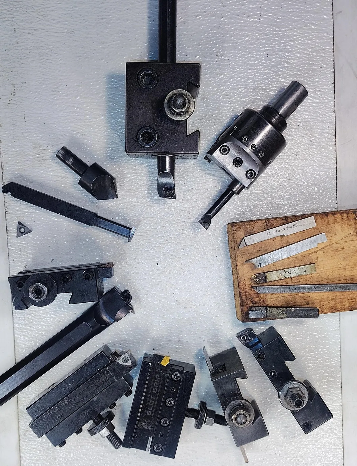
Arranged single-edge metal-cutting tools, boring bars, and toolholders for precision metalworking
Representative single-edge metal-cutting tools. Photo: Progress and Poverty (CC BY 4.0, adapted)

Tube-End Forming Methodologies

Specialized equipment configurations address distinct mechanical deformation requirements.

RAM FORMING

Axial Expansion & Reduction

A linear ram advances a punch into the tube end to expand diameter, or pushes the tube into an external sizing die to reduce outer diameter.

  • Linear punch strokes with controlled velocity stages
  • Expansion capability adapted to material ductility
  • Stop collars to establish depth boundaries
ROTARY FORMING

Rotary Beading & Profiling

Roller dies apply radial pressure to a rotating tube, forming circumferential retention beads or sealing grooves, with wall thinning governed by material ductility and tooling profile.

  • Smooth bead profiles designed to minimize stress concentrations
  • Applicable to thin-wall fluid and ventilation lines
  • Compatible with edge-finishing operations
RADIAL SWAGING

Segmented Jaw Swaging

Multiple radial die segments collapse inward around the tube circumference to produce uniform diameter reductions.

  • Circumferential pressure distribution around the workpiece
  • Applicable across welded and seamless tubular stock
  • Interchangeable jaw inserts for different diameter steps
FLARING

Conical & Flange Forming

Angled mandrels displace tube ends outward to create conical flares or flat perpendicular flanges for mechanical connections.

  • Firm clamp grip to counteract axial slipping under forming force
  • Controlled corner radius geometry to limit splitting risk
  • Adaptable to varied ductile metal alloys
Tooling & Die Arrangements

Tooling systems determine forming accuracy, surface finish, and setup flexibility.

CLAMP DIES

Form-Matched Clamping Inserts

Split jaws machined to match the tube outside diameter, providing friction grip while minimizing surface marking.

PUNCHES

Forming Punches & Arbors

Wear-resistant internal mandrels and punch pins shaped to the required inner diameter profile.

CHANGEOVER

Modular Tool Mounting

Keyed die blocks and quick-clamping arrangements designed to simplify tooling changeover between part runs.

Drive Kinematics & Motion Control

Machine kinematics translate stored power into predictable linear or rotational motion.

HYDRAULICS

Proportional Hydraulic Circuits

Hydraulic cylinders paired with proportional valves to deliver controlled approach speeds and high-tonnage forming strokes.

SERVO DRIVES

Electromechanical Servo Actuation

Electric servo motors driving mechanical ball screws for programmable stroke positioning and velocity control.

MONITORING

In-Process Force Observation

Sensors observing stroke force and pressure profiles to detect abnormal resistance or material variation.

Operator Safety & Machine Guarding

Industrial machine design incorporates physical and electrical protective envelopes.

OPTICAL

Safety Light Curtains

Optical barrier arrangements monitoring operator loading areas, configured to signal motion interruption when a beam is crossed.

ENCLOSURES

Interlocked Access Guarding

Sheet-metal protective panels with safety interlock switches designed to restrict physical access to moving mechanisms during cycle execution.

CONTROLS

Two-Hand Cycle Actuation

Dual-switch control arrangements designed to require concurrent activation, positioning operator hands at designated control points.

Operator Interface & Cycle Indication

Operator interaction points require clear physical placement and unambiguous cycle state indications.

INTERFACE

Cycle State & Status Indication

Visual indicator lamps or displays designed to signal machine readiness, active forming strokes, or cycle-hold status without ambiguous states.

LOADING

Workpiece Loading & Datum Feedback

Mechanical guide nests and stop indicators designed to assist operators with workpiece placement against datum references before clamp closure.

INTERRUPT

Cycle Hold & Manual Reset Procedures

Defined operational sequences for cycle pause, tool retraction, and manual clearance following an intentional or safety-triggered interruption.