Section View
Assembly Cross-Section
Sectional cut revealing the internal meshing between the input worm screw and the rotating wheel, along with shaft centers.
Mechanical and electrical design documentation, from first requirements to review and handover.
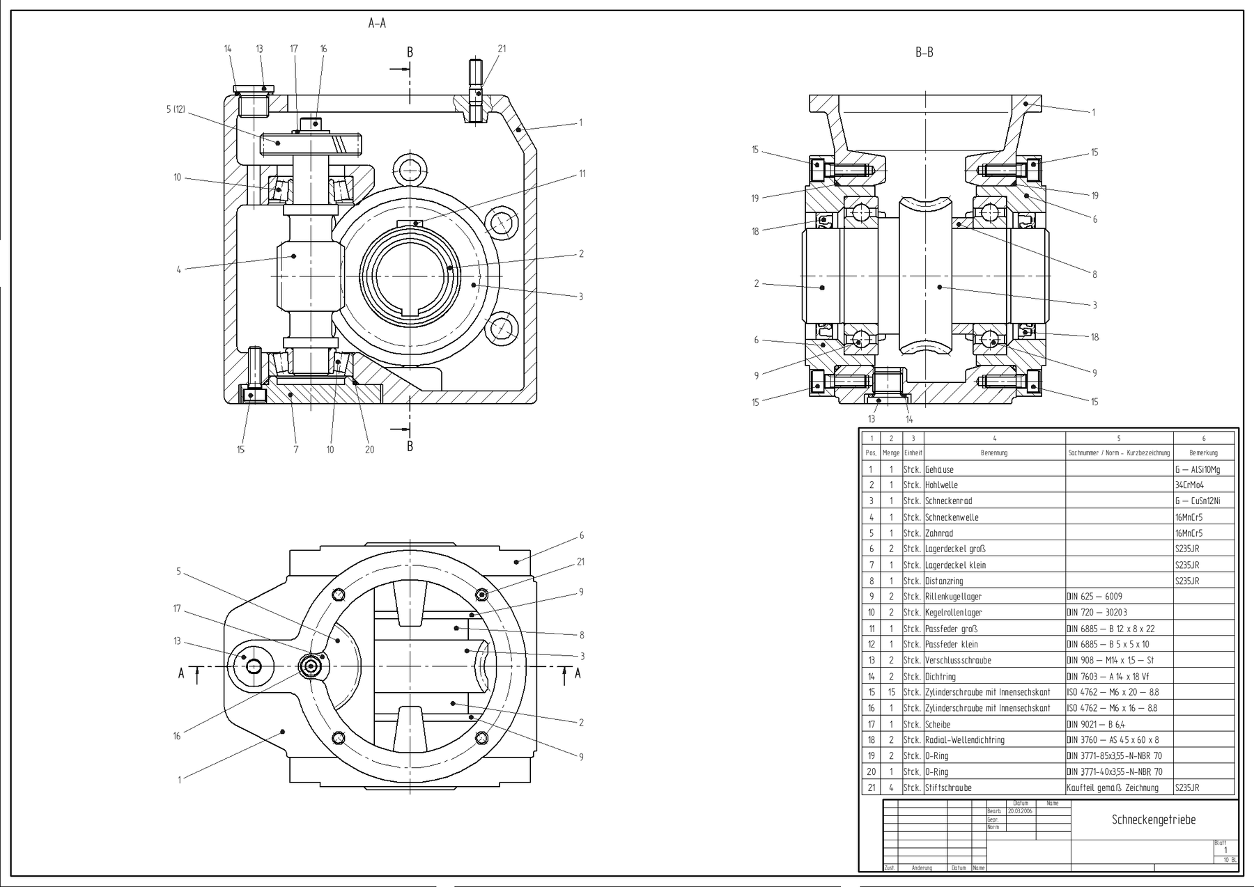
Representative worm-gear assembly drawing.
Representative reference drawing. Resized and losslessly re-encoded as WebP from original PNG.
Sectional cut revealing the internal meshing between the input worm screw and the rotating wheel, along with shaft centers.
The title block groups the drawing name and sheet information in one place.
Structured table enumerating part numbers, item names, material callouts, and required quantities.
A review can ask whether the views, part references, and supporting information are clear.
| Discipline | Scope | Format | Review Consideration |
|---|---|---|---|
| Mechanical Detail Drafting | Orthographic part views, assembly sections, and component dimensions | Vector 2D sheets and neutral 3D models | Orthographic alignment, section cuts, and clear balloon callouts |
| Electrical Schematics | Circuit diagrams, terminal rail allocations, and cabinet layouts | Multi-sheet schematic packages | Terminal cross-references, wire numbering, and device tags |
| Interface Envelopes | Spatial boundaries, mounting bolt patterns, and clearance corridors | 3D boundary envelopes and interface sheets | Mounting coordinates, keep-out zones, and utility points |
| Design Review & Handover | Drawing pack cross-checks, bill of materials alignment, and revision notes | Review registers and release drawing sets | Dimensional consistency, BOM line matching, and revision notes |
An engineering drawing acts as the shared contract between design intent and physical fabrication, ensuring everyone works from identical dimensions.
Initial requirements define the spatial envelope, operating loads, and interface points before detailed drafting begins.
Mechanical parts, electrical routing, and fluid lines are detailed in coordinated drawing sheets to avoid physical clashes.
A review pack brings requirements, drawing notes, and open questions together before drawings are released to the shop floor.
Technical documentation typically progresses through iterative review states.
Concept sketches and envelope outlines used to confirm spatial boundaries and overall proportions.
Dimensional chains, sectional cuts, and electrical terminal allocations verified by peer checkers.
Checked drawing sheets issued with formal revision letters and locked for purchasing and machining.
Final drawing revisions reflecting shop assembly markups and physical installation notes.
Starting a drawing requires clear physical boundary constraints and part specifications.
Maximum allowable dimensions, mounting bolt coordinates, and operator maintenance access zones.
Catalog numbers and dimensions for off-the-shelf motors, bearings, sensors, and fittings.
Target fabrication processes—such as milling, turning, sheet metal, or welding—to guide appropriate dimensioning.