Design-document disciplines.

An overview of technical documentation disciplines: mechanical CAD drafting, electrical schematics, interface envelopes, and pre-fabrication review packs.

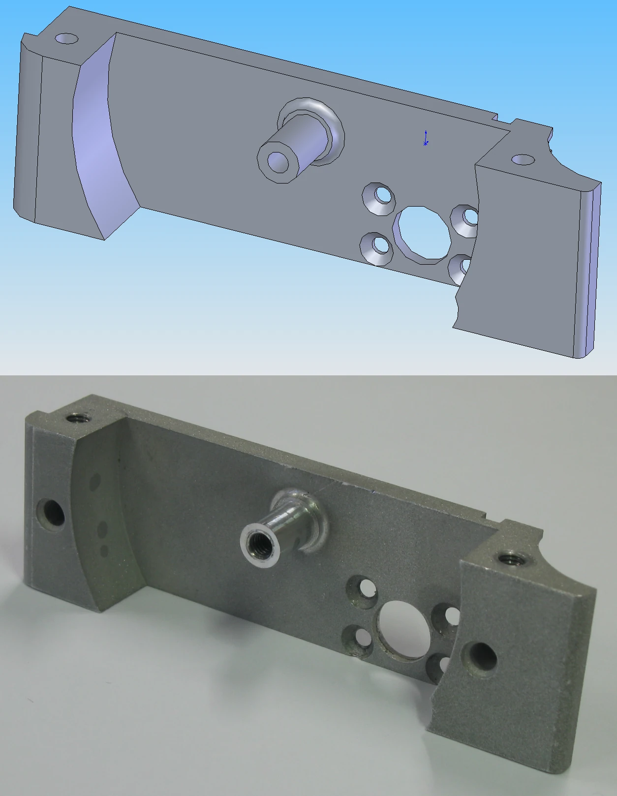
Sheet 02CAD Model & Milled Component Comparison
CAD model above a corresponding CNC-milled aluminium component below.

Representative CAD-to-machined component comparison.

Representative reference asset. Re-encoded as WebP from original PNG.

Mechanical Drafting & Detail Sheets

Preparing manufacturing drawings from 3D models with orthographic projections, sectional cuts, and component dimensions.

Assembly & Subassembly Drawings

Orthographic views, cross-sections, and balloon callouts linking parts to a structured bill of materials.

  • Section planes showing internal part relationships and fasteners
  • Exploded assembly arrangements illustrating build sequence
  • Overall envelope dimensions and reference centerlines

Part Detail Drawings

Individual component drawings with dimensions, hole locations, and surface notes needed for part production.

  • Complete dimensional chains referenced from datum surfaces
  • Hole notes specifying drill, ream, and thread callouts
  • Material callouts and protective coating specifications

Fits & Clearances

Coordinating shaft and bore clearances, keyway fits, and sliding allowances across mating components.

  • Clearance checks for moving linkages and rotating components
  • Coordinated dimensional tolerances across mating parts
  • General notes for non-critical surfaces

Electrical Schematics & Cabinet Layouts

Documenting electrical power distribution, control loops, and cabinet component arrangements.

Power & Control Schematics

Circuit diagrams showing main incoming power feeds, 24V DC control loops, safety circuits, and sensor connections.

  • Consistent component letter codes and device tags
  • Cross-referencing numbers for tracing signals across multi-page schematics
  • Separation between power conductors and low-voltage signal wiring

Cabinet & Panel Drawings

Dimensional component placement drawings for DIN-rail devices, power supplies, and enclosure door cutouts.

  • Component spacing accommodating thermal ventilation needs
  • Wire duct routing channels and conduit entry points
  • Door panel cutouts for indicators, switches, and displays

Terminal & Interconnect Tables

Structured charts defining terminal rail connections, field cable runs, and wire identification numbering.

  • Terminal strip numbering and conductor assignments
  • Field junction box and cable gland schedules
  • Grounding and protective bonding path documentation
Interface Envelopes & Routing

Spatial boundary modeling that enables coordinated work between machine builders and subsystem suppliers.

Spatial Boundary Envelopes

3D keep-out volumes defining allowable space, tooling travel strokes, and maintenance access corridors.

  • Maximum dynamic motion envelopes including clearance margins
  • Clearance zones for routine maintenance and tool access
  • Cable carrier travel paths and minimum bend radius allowances

Mounting & Alignment Interfaces

Mounting flange details, dowel pin locating coordinates, and structural interface mating surfaces.

  • Coordinated bolt hole patterns and alignment features
  • Common reference coordinate origin across subassemblies
  • Load transfer points and structural support surfaces

Utility Connection Points

Locations and fitting specifications for pneumatic supply lines, electrical feeds, and fluid connections.

  • Bulkhead fitting locations and port thread specifications
  • Clear labeling of supply, return, and exhaust lines
  • Service isolation and drain point positions

Drawing Review Packs & Checking

A review pack brings requirements, drawing notes, and open questions together before drawings are released to fabrication.

Completeness & Consistency Check

Verifying that every feature has adequate dimensional control and that notes are legible.

  • Cross-checking dimensions across mating parts
  • Reviewing weld symbols and joint preparation callouts
  • Verifying standard tooling availability to simplify machining

Bill of Materials Alignment

Cross-checking part numbers, descriptions, and quantities between drawing balloons and the procurement list.

  • Verification of standard purchased component part numbers
  • Quantity match between assembly views and parts lists
  • Confirmation of raw material grade callouts

Revision Documentation

Recording changes with clear revision letters, modification descriptions, and date stamps.

  • Revision history block recording author, checker, and date
  • Revision markers identifying modified drawing zones
  • Archiving superseded sheets to prevent out-of-date shop use

Scope & Disciplinary Distinctions

Clear distinctions separate technical drawing disciplines from adjacent fields.

Distinct from Civil Architecture

This documentation covers machinery and industrial equipment. It does not cover civil buildings, architectural envelopes, residential layouts, or municipal permit sets.

Distinct from Automation Integration

These drawings are mechanical and electrical. They do not cover PLC code, SCADA server setup, cabinet wiring on factory floors, or machinery commissioning.